Updating
Updating software and firmware for your e3Vision system.
Plug the supplied AC adaptor into the wall socket and connect it to the camera hub.
Use any Ethernet cable to connect the first port of the camera hub, marked Uplink, to an existing gigabit network. You may also connect it to an available Ethernet port on a PC gigabit network card or USB gigabit network adapter.
Note: only the first Uplink port should be connected to the network or storage computer. All other ports are for use with e3Vision cameras, not standard networking equipment.
If you wish to use the secure remote access features to control or view from another laptop or phone browser, you must connect the Uplink to an existing network, such as a campus network, or an lab internal router or gateway.
Use the supplied Ethernet cables to connect the camera(s) to hub ports 2 - 15. Note that the 2nd hub port (1st camera port), labeled Master, will be the camera responsible for sending the synchronization signal that all other cameras will follow.
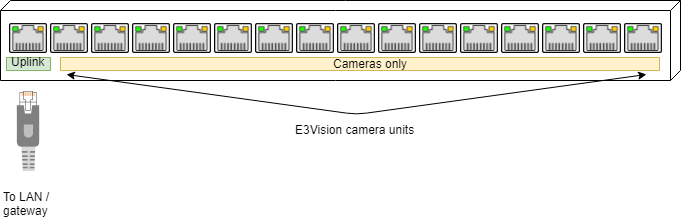
The first hub port is Uplink, followed by camera units.
Mount the cameras with the included GoPro-style mount adaptors.
Note: while the cameras have a standard 1/4-20 UNC tripod thread, typical tripod mounting bolts are often too long and may damage camera internals. Damage resulting from the use of a third-party mount will not be covered by the warranty.
Connect the computer running the Watchtower software to the same network as the camera hub.
Use the top micro-switch on the rear of the camera hub to select the sync direction of the entire hub:
The Watchtower software (e3v-watchtower) is used to control and manage all cameras. To ensure reliable video capture, this software should be installed and used on a computer that is connected to the Local Area Network (LAN) or the e3Vision hub directly by wired gigabit Ethernet, not a wireless connection.
You can download the current software at the e3Vision page.
Bonjour, included in the .zip. This is a support library that locates e3Vision cameras on the network.e3v-watchtower.exe.ZeroMQ using apt by typing:
apt-get install libzmq5
./e3v-watchtower
ZeroMQ using Homebrew by typing:
brew install zmq
./e3v-watchtower
Run e3v-watchtower or e3v-watchtower.exe. If prompted, allow firewall/network access to the running process. A console displaying log events will appear; do not close the console unless you wish to terminate Watchtower and end all camera operations.
You will be asked whether or not you want to Start Watchtower with web remote access? Answer Y if you wish to control cameras from a different computer.
Answering Yes will allow other devices on the network to access the Watchtower web interface and APIs. This can allow remote control and viewing of cameras from another laptop or phone, or allow automation by e.g. a networked Python trigger. Please set a long, safe password to help safeguard against unauthorized access.
Answering No will restrict Watchtower web interface and scripting access to this local computer only (bind to loopback).
The web management interface will automatically open a browser to the address https://localhost:4343/.
Advanced → Accept and continue.Yes to the remote access option, the web management interface can also be accessed using any other computer or mobile device
by navigating to an IP address of the control server where Watchtower is installed: http://[Watchtower IP]:4343/. If you’re uncertain of the IP address, it can be viewed from the next step when choosing the Ethernet interface.Bind each camera you wish you use from this Watchtower installation.
This pairs each camera with this installation of Watchtower with strong encryption, and makes the camera unavailable to other installations of Watchtower on the same network (e.g. different labs or experimenters).
We recommend cameras be left bound when unused. Cameras can be safely left on in this mode, bound to a specific instance of Watchtower. To un-pair in the future, use the Unbind button, or physically cycle the camera power.
Apply these settings before starting up the cameras. If you wish to change these settings for a group of cameras, you must stop and restart the video streams for them to take effect.
The first hub port is Uplink, followed by camera units.
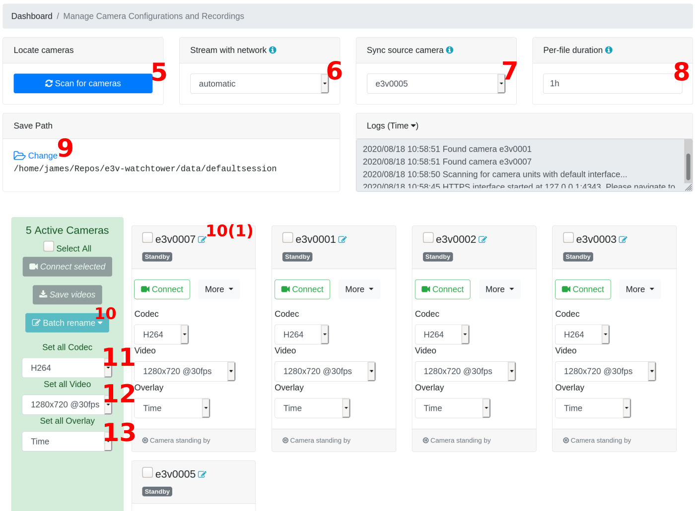
Select Scan for cameras. Any cameras on the LAN will auto populate. The default name of the cameras is “e3v” + the 4-digit serial number found on the Ethernet port of the camera unit, such as “e3v8100”.
In Stream with network, automatic mode should successfully stream from the cameras. However, if the controlling server has multiple simultaneous network interfaces (such as Wi-Fi, or multiple network adapters), choose under the wired gigabit Ethernet interface that is connected to the same network as the e3Vision hub.
Use the Sync source camera drop-down to define the camera plugged into the port labelled Master (2nd hub port, 1st camera-dedicated port).
Optional: Edit the File duration text box (input e.g. “1h2m3s”, “1h”, “3m") to split the stream video into .mp4 or .avi files of the specified duration. This splitting process is seamless and video will continue without loss across split files.
Optional: Edit the File Path box to choose an alternate path for storing the video recordings.
Optional: Select the camera(s) you want to modify the name of using the checkboxes (or “Select All”) and select Batch Rename and enter the custom name for the group. Select “Submit” to make the changes.
Optional: Modify the FPS and Resolution of the cameras by using the Resolution @FPS drop-down to select a different group of video settings.
Select the Codec using the dropdown. If you are setting up the cameras for the first time, we recommend the MJPEG option to make setup and camera focusing easier.
H264 codec: produces .mp4 files. This is the most efficient form of video storage in Watchtower and suited for long-term recordings (~5x smaller file sizes than MJPEG). However, the video stream will have a buffering delay of 1-2 seconds and are not suitable for real-time image processing or triggering.
MJPEG codec: produces .avi files; bigger than H264-encoded .mp4s. They are near-real-time (2 frames of buffer delay, or as low as 33 ms) and are suitable for real-time image processing, such as real-time DeepLabCut. If you are getting cameras set up for the first time, we also recommend using this mode to make focusing easier.
Optional: The cameras can overlay text into the video files.
Synced status will appear in a Green title bar, and the video streaming bandwidth will appear at the bottom.
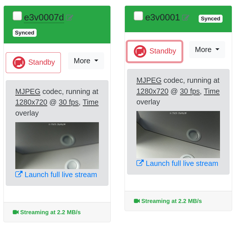
Connected and synced cameras appear in Green.
Standby all cameras and check that the Sync source camera has been set correctly to the camera plugged into the port labelled Master, before re-Connect-ing.
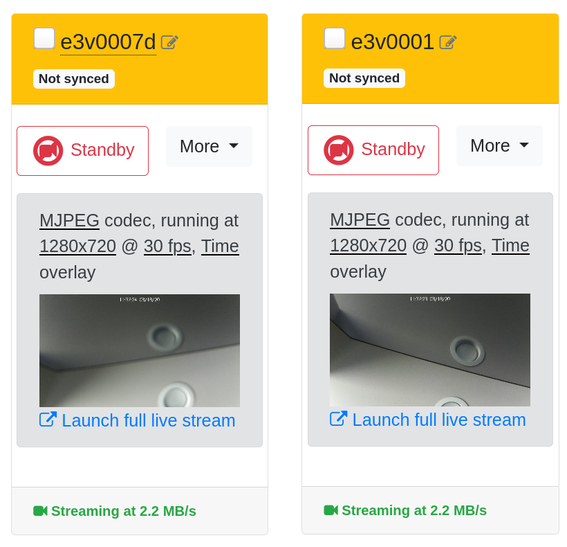
Non-synced cameras appear in Yellow when no synchronization signal is found from the Sync source camera.
Saving will be shown in Blue once the process has begun and display the disk saving data rate at the bottom.
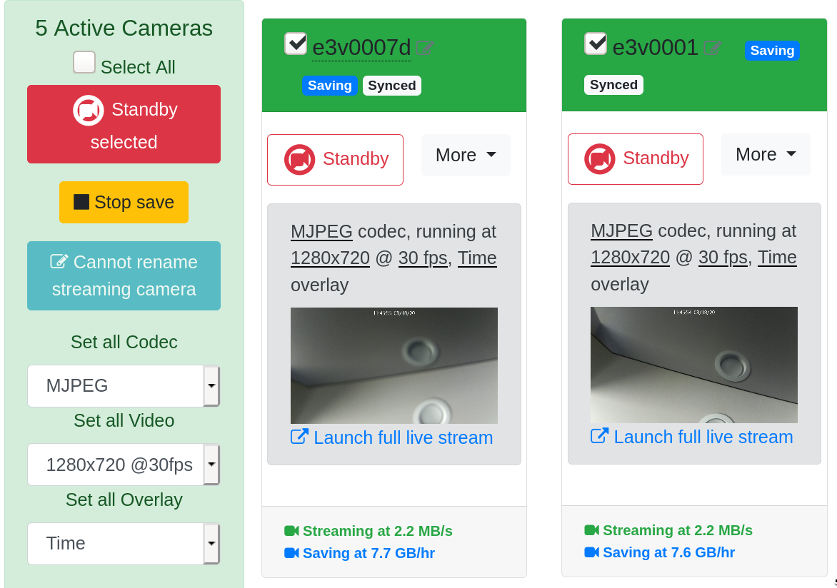
All checkbox (☑) selected cameras will start saving frame-synchronized video as a group, when Save videos is pressed.
No Save.Updating software and firmware for your e3Vision system.