Headstages
White Matter headstages may have the form factors of:
- Standalone units with integral amplifier frontends, such as the
hs-64mpictured below- standalone headstages can still have additional slots for modular accessories, such as accelerometers or microphones
- high-channel scalable headstages such as the
hs-640below, with a tether module and between 1 - 10hs-ampstackable amplifier frontends
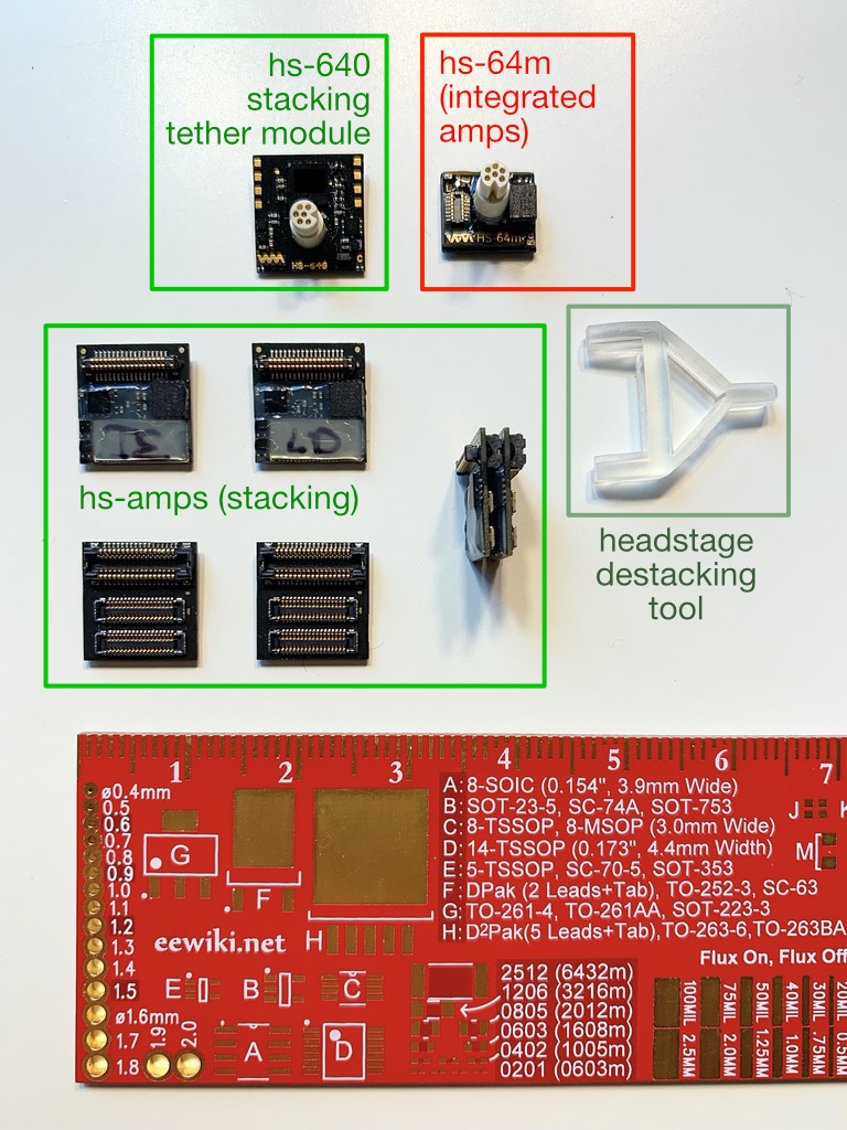
Stacking headstages
Stacking hs-amp
Each hs-amp board has two types of connectors:
- Digital stacking connector: Located on the top and bottom, for connection between
hs-ampboards and the top tether module - Electrode connector (receptacle): Located only on the bottom of the board, this dual set of smaller receptacles (32ch per receptacle, 64ch per pair) facilitates connection with electrode interface boards (EIBs) or other electrode breakouts
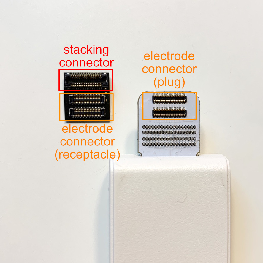
Viewed from the bottom face of the hs-amp board, one large digital stacking connector, and a twin-set of electrode connectors. Note that the electrode connectors mate with electrode interface boards, or the connectors on our hs-tester compact signal generator.
hs-640 tether module
Each tether module board can be identified by a white, cylindrical tether connector (top) and a digital stacking connector (bottom).
Each tether module can support up to 10 hs-amp boards, for a total of supported 640 channels.
Connecting electrode interface boards
Electrode connectors must be carefully connected to maximize signal integrity, and should be carefully assembled to avoid connector damage. For best results, hs-amp boards should be destacked from their parent stack to connect to their electrodes interface boards individually.
An example connection shown here is between an hs-amp board an an hs-tester signal generator. Note that from the side the electrode connector (receptacle) on the hs-amp is metallic, and the electrode connector (plug) on the hs-tester is dark plastic.
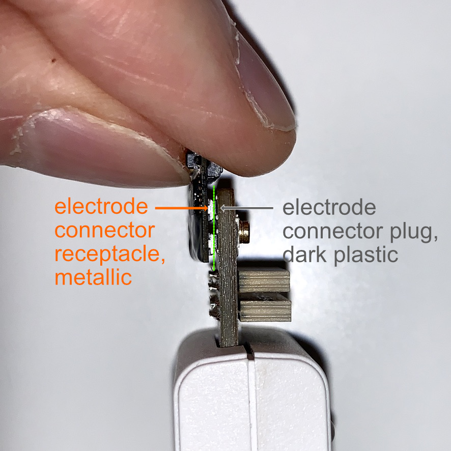
Verify all sides to make sure that the metallic receptacle margins are enveloping the plug (closer to the viewer) on all sides, before applying pressure to join the connection.
Always verify that the receptacle is aligned with the plug by making sure that you can see metallic receptacle margin surrounding the dark plastic plug on all sides of the connectors, before applying gentle but firm pressure. The connectors should click together with a tactile click.
If the connectors do not click together, do not apply additional pressure and re-verify alignment.
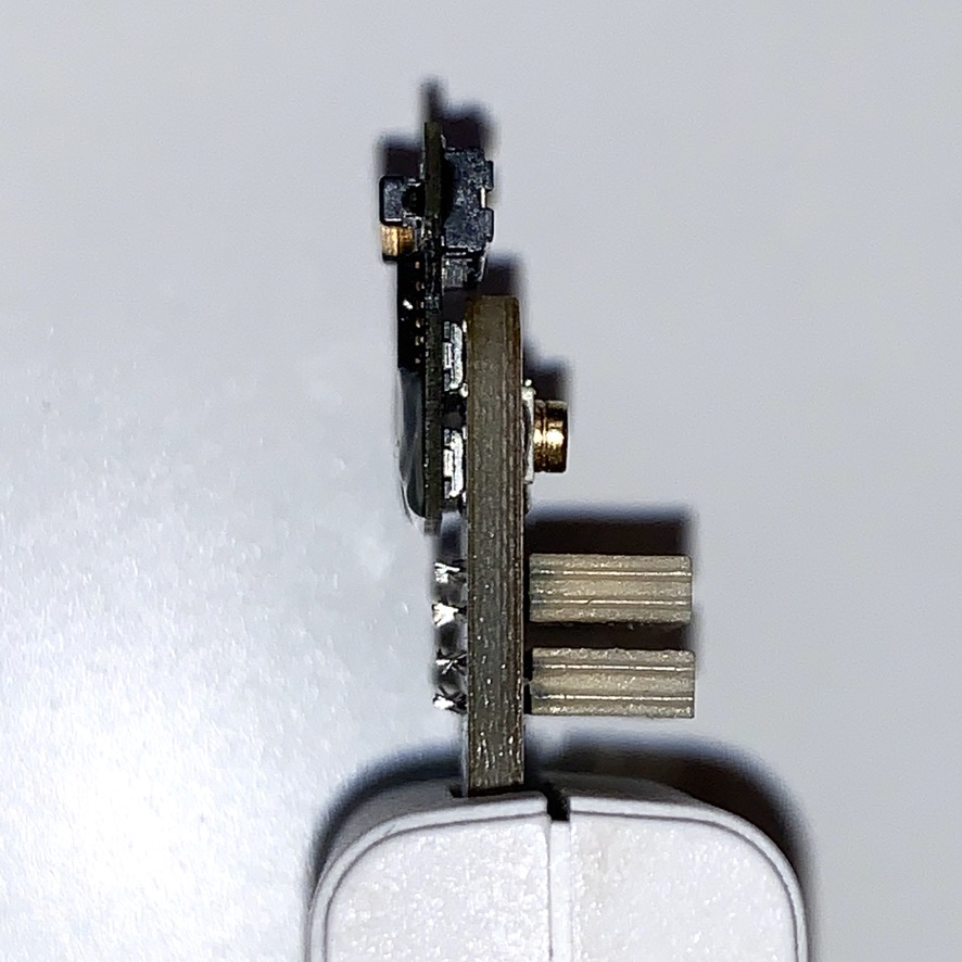
A successfully connected electrode board. Dark plastic is no longer visible and is fully occluded by the metallic receptacle margin.