Sync Hub
The sync hub comes serve to provide power, data, and synchronization through a convenient single cable for each connected camera. It comes in a 7-camera and a 15-camera variant, and is adaptable in many types of experimental scenarios.
Hub data uplink
Each hub has an uplink data port (leftmost port on the front side of the hub), which can be connected to a computer, internal network, or organizational network. Please see the Network layout page for more details on network setu.. The uplink port can carry up to 1 Gbps of compressed video data, aggregated from all camera units connected on the hub.
Hub camera sync
The uplink port is followed by 7 or 15 camera ports, depending on the hub variant.
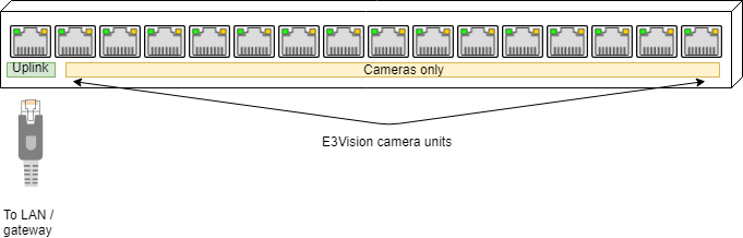
The first hub port is Uplink, followed by camera units. The first camera-supporting port is labeled primary (or master).
A chosen camera connected to the first camera port becomes the sync source camera. All other cameras connected to the same hub follow the synchronization signal of the sync source camera, and the sync signal can be further monitored using an electrophysiology recording system in order to determine the frame capture time of all connected cameras.
Hub rear BNC configuration
The default mode of operation for shipped e3Vision hubs has the DIP switch set to the output position, the camera hub forms its own independent sync group. You can observe the synchronization signal working if the Camera sync indicator LED flashes with the frame acquisition of the sync source camera.
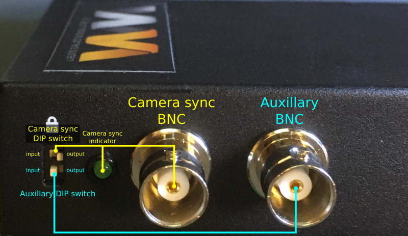
The camera sync BNC is shipped in the default output mode for camera sync signal monitoring by an external electrophysiology system.
The same sync BNC can also be switched input for daisy-chained operation, where two hubs join the same sync group.
The camera sync indicator LED should flash in synchrony with the frame acquisition of the sync source camera.
All camera hubs are shipped with the default BNC configurations:
- Camera sync BNC configured to the output position
- Auxiliary BNC configured to the input position
With multiple e3Vision hubs, each hub can create its own independent sync group, and the sync BNC outputs can be monitored by an external electrophysiology system, or any other analog signal acquisition system.
For additional Troubleshooting, see the Troubleshooting camera synchronization page for synchronization-specific instructions.
Daisy-chaining hubs to join one sync group
In addition, hubs can be “daisy-chained” to each other to follow a single sync source camera. To do this, set the Camera sync DIP switch carefully with a small flat-head screwdriver to the left input position.
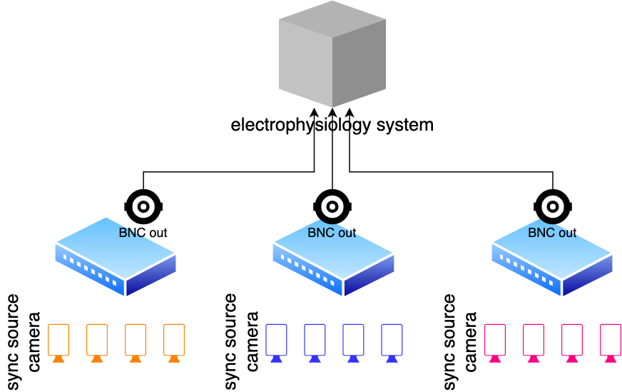
These 3 hubs form 3 distinct sync groups, with 3 separate sync source ("Primary") cameras.
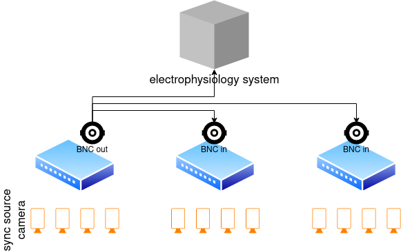
The 3 hubs are daisy-chained together into one large sync group, with the leftmost hub's sync source camera being shared among the additional 2 hubs.
Hub rear BNC signal output
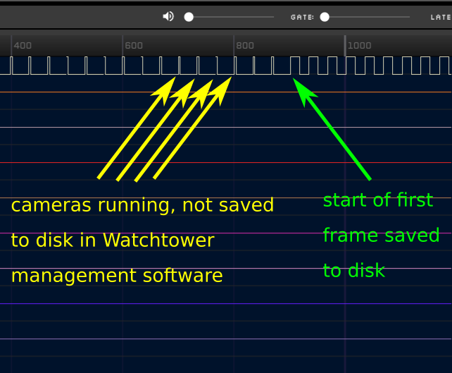
3.3V signal from the rear BNC of the e3Vision hub; the rising edge corresponds to frame capture times.
10% duty cycle pulses: frame capture during all camera streaming.
50% duty cycle pulses: frame capture while frames are recorded to disk.
The e3Vision hub outputs a 10% duty cycle pulses at frame capture during camera streaming, and 50% duty cycle pulses when frames are recorded to disk.
With the cameras running continuously, the timing of the these 10%->50% duty cycle pulses can be captured by an external electrophysiology system, and used as reference for the moment of recording start/stop.
For more options on automating and synchronizing video recording start/stop, please see the detailed synchronization methods page.